Hardware
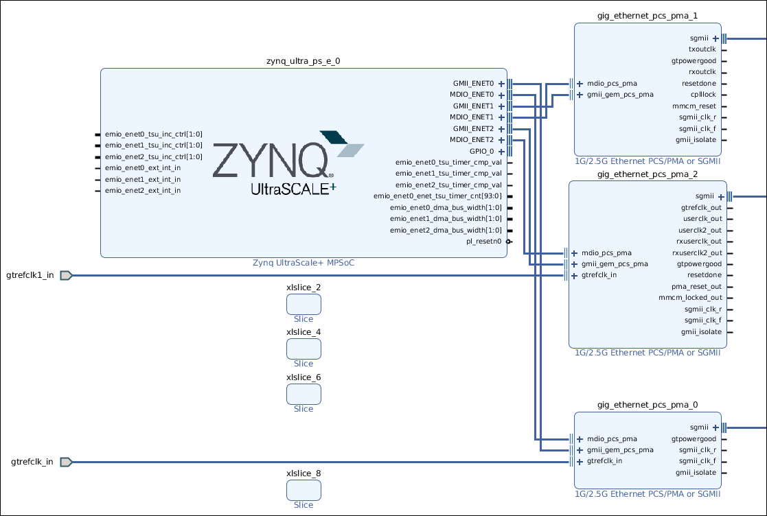
The LM96163 temperature sensor is hooked up over I2C to two PL pins on the board. This I2C interface was originally controlled by a state machine in the fabric, without means to access it from Linux. This modification allows it to be preset from U-Boot to a particular critical setpoint temperature which may vary per application. It also allows the temperatures, alerts and fan controls to be operated from Linux. The LM96163 TCRIT output is a special alarm output that is tied to the power supply IC that in case of an over-temperature condition, will shut-off power to protect the system.
ZynqMP configuration
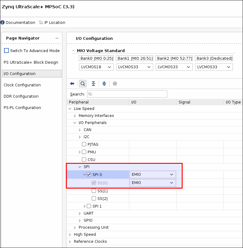
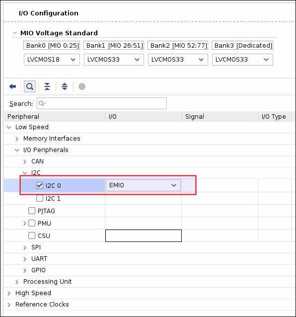
The Zynq will need to have one of its two I2C controllers enabled and set to EMIO to access the PL pins.
The PL pins are in turn defined in the .xdc file, with an added internal pull up.
# Temperature controller LM96163 - Bank 84
set_property IOSTANDARD LVCMOS25         [get_ports temp_*]
set_property PULLUP TRUE                 [get_ports temp_*]
set_property PACKAGE_PIN AP10            [get_ports temp_smbclk]
set_property PACKAGE_PIN AP11            [get_ports temp_smbdata]
Kernel configuration
The kernel 5.10.x has support for the LM96163 through the LM63 driver, which conveniently comes enabled by default. The setting can be found in the kernel configuration as follows:
Symbol: SENSORS_LM63 [=y]
   Type  : tristate
   Defined at drivers/hwmon/Kconfig:1141
     Prompt: National Semiconductor LM63 and compatibles
     Depends on: HWMON [=y] && I2C [=y]
     Location:
       -> Device Drivers
   (1)   -> Hardware Monitoring support (HWMON [=y])
The last remaining item is the device tree, that specifies which I2C address (0x4c) and driver will handle the device, besides which I2C controller will be involved in the communication. We add a few lines to project-spec/meta-user/recipes-bsp/device-tree/files/system-user.dtsi
&i2c0 {
  lm96163@4c {
    compatible = "national,lm96163";
    reg = <0x4c>;
  };
};
Kernel access
Once the system has booted up with these changes, the sysfs will have special files to control the driver and consequently the LM96163 device. The sysfs entries are shown here:
root@DAQ16-2021:~# ls -l /sys/bus/i2c/drivers/lm63/0-004c/hwmon/hwmon0/
total 0
-r--r--r-- 1 root root 4096 Apr 20 23:26 alarms
lrwxrwxrwx 1 root root    0 Apr 20 23:26 device -> ../../../0-004c
-r--r--r-- 1 root root 4096 Apr 20 23:26 name
lrwxrwxrwx 1 root root    0 Apr 20 23:26 of_node -> ../../../../../../../../firmware/devicetree/base/axi/i2c@ff020000/lm96163@2e
drwxr-xr-x 2 root root    0 Apr 20 23:26 power
-rw-r--r-- 1 root root 4096 Apr 20 23:26 pwm1
-rw-r--r-- 1 root root 4096 Apr 20 23:26 pwm1_auto_point10_pwm
-rw-r--r-- 1 root root 4096 Apr 20 23:26 pwm1_auto_point10_temp
-r--r--r-- 1 root root 4096 Apr 20 23:26 pwm1_auto_point10_temp_hyst
-rw-r--r-- 1 root root 4096 Apr 20 23:26 pwm1_auto_point11_pwm
<...snip...>
-rw-r--r-- 1 root root 4096 Apr 20 23:26 pwm1_auto_point9_temp
-r--r--r-- 1 root root 4096 Apr 20 23:26 pwm1_auto_point9_temp_hyst
-rw-r--r-- 1 root root 4096 Apr 20 23:26 pwm1_enable
lrwxrwxrwx 1 root root    0 Apr 20 23:26 subsystem -> ../../../../../../../../class/hwmon
-r--r--r-- 1 root root 4096 Apr 20 23:26 temp1_input
-rw-r--r-- 1 root root 4096 Apr 20 23:26 temp1_max
-r--r--r-- 1 root root 4096 Apr 20 23:26 temp1_max_alarm
-r--r--r-- 1 root root 4096 Apr 20 23:26 temp2_crit
-r--r--r-- 1 root root 4096 Apr 20 23:26 temp2_crit_alarm
-rw-r--r-- 1 root root 4096 Apr 20 23:26 temp2_crit_hyst
-r--r--r-- 1 root root 4096 Apr 20 23:26 temp2_fault
-r--r--r-- 1 root root 4096 Apr 20 23:26 temp2_input
-rw-r--r-- 1 root root 4096 Apr 20 23:26 temp2_max
-r--r--r-- 1 root root 4096 Apr 20 23:26 temp2_max_alarm
-rw-r--r-- 1 root root 4096 Apr 20 23:26 temp2_min
-r--r--r-- 1 root root 4096 Apr 20 23:26 temp2_min_alarm
-rw-r--r-- 1 root root 4096 Apr 20 23:26 temp2_offset
-rw-r--r-- 1 root root 4096 Apr 20 23:26 temp2_type
-rw-r--r-- 1 root root 4096 Apr 20 23:21 uevent
-rw-r--r-- 1 root root 4096 Apr 20 23:26 update_interval
We can read the current remote diode temperature by reading these pseudo-files:
root@DAQ16-2021:~# cat /sys/bus/i2c/drivers/lm63/0-004c/hwmon/hwmon0/temp2_input
53125
…which would correspond to 53.125 degrees Celsius.
Perhaps intentionally to avoid rogue software from controlling the TCRIT output, the remote setpoint TCRIT setting is not writable in the default driver, but read-only.
Testing from U-Boot
In order to set the remote setpoint before Linux boots, we can either set it from the FSBL, or from U-Boot. In this case, we will modify a special U-Boot variable that executes at boot to run the proper I2C commands.
From U-Boot prompt, we interact with the I2C controller to access the LM96163 registers.
Scan I2C bus to find all enabled controllers:
ZynqMP> i2c bus
Bus 0:  i2c@ff020000
ZynqMP> i2c dev 0
Setting bus to 0
ZynqMP> i2c probe
Valid chip addresses: 4C
Read various interesting registers:
Die ID (0x49)
ZynqMP> i2c md 4c ff 1
00ff: 49    I
Read Remote T_CRIT setpoint (0x6E at POR)
ZynqMP> i2c md 4c 19 1
0019: 6e    n
Read POR status (0x33)
ZynqMP> i2c md 4c 33 1
0033: 00    .
Read Alert status (0x2)
ZynqMP> i2c md 4c 2 1
0002: 00    .
Read Configuration (0x3)
ZynqMP> i2c md 4c 3 1
0003: 00    .
We then set the remote TCRIT setpoint to 55 C (0x37) degrees.
Write Configuration (ALTMSK+TCRITOV)
ZynqMP> i2c mw 4c 3 82 1
ZynqMP> i2c md 4c 3 1
0003: 82    .
Write Remote Diode Temperature Filter (RDTF1+RDTF0)
ZynqMP> i2c md 4c bf 1
00bf: 00    .
ZynqMP> i2c mw 4c bf 6 1
ZynqMP> i2c md 4c bf 1
00bf: 06    .
Set Remote T_CRIT setpoint to 0x37
ZynqMP> i2c mw 4c 19 37 1
ZynqMP> i2c md 4c 19 1
0019: 37    7
Programming from boot
Once we know how to program the remote TCRIT setpoint from U-Boot, it’s time to configure it to execute these commands on each boot. To this end, we use the special configuration option CONFIG_PREBOOT to run the commands before the U-Boot prompt shows up. This setting can be set in the bsp.cfg file used by U-Boot in project-spec/meta-user/recipes-bsp/u-boot/files/bsp.cfg
CONFIG_BOOTDELAY=5
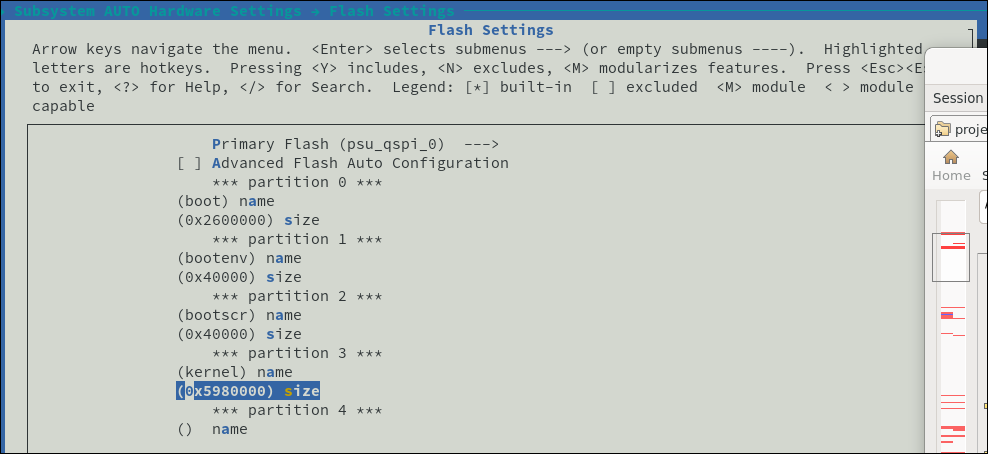
CONFIG_BOOT_SCRIPT_OFFSET=0x2580000
CONFIG_ENV_OFFSET=0x2600000
CONFIG_PREBOOT="i2c dev 0; i2c md 4c 3 1; i2c mw 4c 3 82 1; i2c mw 4c bf 6 1; i2c mw 4c 19 37 1"
Testing
All is ready for some testing. Once Linux has completed booting, we manually disconnect the fan from the heat sink, to force a simulated over temperature condition of 55 degrees Celsius. In about 20 seconds, the temperature rises and crosses the remote TCRIT setpoint, effectively powering down the supplies.
Conclusion
We successfully managed to configure the Zynq to connect over I2C to the temperature sensor, pre-set its remote critical setpoint in U-Boot, to monitor the sensor’s registers from Linux, and finally to simulate an over temperature condition.
]]>